GPS – It’s Not Just For Geocachers!

OK folks, let’s put on our big boy pants and play grownup GPS.

“Look at me!  I know how to use GPS for
something other than geocaching!”
I’m involved in a test at a very large and very busy airport to determine the feasibility of using inexpensive handheld GPS receivers as reconnaissance tools for our engineering and facilities staff.  The consumer market is crammed with relatively inexpensive GPS devices and any one of those should fit the need.  We are not necessarily looking for accuracy here; most dedicated GPS units made these days offer plenty enough accuracy.  More important for our project is ease of use, the ability to import a fairly high resolution background image of the airport and the ability to provide coordinate read-outs in our proprietary (i.e., non-standard) grid system.
Let’s start with the proprietary grid system issue.  It may sound daunting, but it’s really not.  A fair number of low end GPS units provide what’s called a ‘user coordinate system’ setting.  The user just needs to provide a center point for the grid (in lat/long), a false northing and easting for the center point, a scale factor and few other bits of information.  It’s pretty straight forward, and we’ve been able to program a 13 year old Magellan 315 to handle the task.  The Magellan 315 was a hot-spit GPS unit in its day but by today’s standards it is out dated.  It is relatively slow to boot up, slow to acquire and lock onto satellites and it doesn’t receive WAAS signals.  Still, it is easy to operate, the screen is a classic example of uncluttered high contrast clarity and it takes user coordinate system definitions without breaking a sweat.  Once it was up and operating it provided perfectly acceptable accuracies.
Magellan 315
Simple to operate and
has no issues with operating under
a proprietary grid system
Next we tested a seven year old Thales Mobile Mapper.  The Mobile Mapper was a piece of kit left behind at the close of a project several years back.  The contractor bought it to help locate underground utility marker balls and turned it over to the airport when the contract ended.  It’s an odd duck piece of gear – not friendly enough to take on a fishing trip but not sophisticated enough to satisfy surveyors.  Still, it was perfectly willing to accept our coordinate system definition and returned fine accuracies.
Thales Mobile Mapper
So we proved it’s possible to program our coordinate system into inexpensive GPS units.  It should be a simple task to identify a more modern unit that fit our performance and budget requirements.  This is where things got interesting and frustrating.  Our quest has revealed an ignored market segment for GPS units and leaves us scratching our heads and wondering just where the consumer GPS market is heading.

____________________________________________________________
GPS is marvelous technology.  It has removed the great uncertainty in wayfinding and positioning that has vexed mankind since the first caveman decided to go from here to there and his wife told him where to turn.  The real genius of GPS has been in the integration of the location signal (and that’s all GPS really is – a bunch of signals from satellites in the sky that provide the information a GPS receiver needs to calculate a position) into devices that leverage that location in unique ways.
Twenty years ago a ‘consumer grade’ GPS was an expensive piece of gear that did little more than provide a location and allowed you to store a few dozen waypoints.  In 1999 I purchased the Magellan 315 used in this test for $300, and was happy to get it at that price.  Today $300 buys a unit that provides a position fix that is twice a precise as the 315, uses a high resolution color touchscreen display, stores thousands of waypoints, has a digital 3-axis compass, a barometric altimeter and a digital camera that takes geotagged images.
But the success of the integration of dedicated GPS receivers is also proving to be their undoing.  Here’s why.  I can walk into just about any AT&T, Verizon, T-Mobile, Wal-Mart, Target or Best Buy and purchase a smartphone that offers these same features for about $200 (if I sign up for a service plan).  But in the package I also get a phone, a messaging device, a video chat device, an internet device, a music player, a game console and much more.  The integration of GPS into common consumer devices like phones and tablets is killing the dedicated GPS industry. It’s not that highly integrated devices like the iPhone are better GPS devices – far from it.  The real problem is perception.  When pondering the purchase of a dedicated GPS unit the average consumer glances at his or her smartphone and asks, “why spend another couple of hundred bucks when I already have GPS and a mapping application rolled up into this device?”

Most consumers are not educated enough to understand that a dedicated GPS unit offers features that make it uniquely suited to outdoor use in rugged environments.  GPS integration in a smartphone is a compromise, particularly the antenna system.  On a smartphone GPS has to coexist with a range of other receivers and transmitters that all require their own antennas – cell, wi-fi, Bluetooth, etc.  A smartphone is first a phone, and other features like GPS get secondary design consideration.  But with a dedicated GPS unit optimized GPS reception and performance is the primary design goal.  First and foremost we expect a GPS unit to provide fast and accurate position fixes under a wide range of conditions.  If you want to know where to find the nearest Starbucks get a smartphone.  If you are on a seven day backpacking trip and its been raining the last three days and you want to know where the next campsite with a bear box is located get a dedicated GPS.

So let’s take a closer look at how the market is broken down.

Today’s dedicated GPS devices fall into three broad categories.
1. Consumer grade devices like we are discussing here.  This market is focused mainly on those participating in outdoor sports like geocaching, hiking, biking, fishing, etc.  These devices cost between $200 and $700, with the bulk of sales taking place at around the $300 price point.  This is the market segment that receives brutal competition from other consumer devices like smart phones, and the manufacturers are scrambling to find a niche and stay relevant.  Garmin, Magellan and DeLorme are the three leaders here.
The Garmin eTrex is perhaps the most
successful line of consumer GPS units in the industry
2. Dedicated map data or field data collection devices.  These are handheld units running mapping software like ESRI’s ArcPad and are used by organizations like utility companies to collect information in the field.  These mapping devices have an entry price point of around $1,000 and can go up to over $3,000.  Most of these units offer more GPS accuracy through the use of improved antennas and better software, but offer fewer features like digital compasses and altimeters.  The big attraction with these GPS units is the flexibility of the mapping software and the ability to directly ingest the collected data into high end desktop mapping software like ESRI’s ArcGIS suite.  The additional cost for these dedicated GPS units is the result of a smaller market share, higher hardware costs and the increased cost of the the operating system (usually Windows Mobile) and the mapping software.  Trimble Navigation dominates in this market.
Trimble Juno
No compass, no altimeter but hey,
at least it runs Windows!

3. The high end market is dominated by survey-grade GPS units that start around $5,000 and can peak out at over $30,000.  For that price (along with a subscription to a real-time correction service that runs a few thousand each year) the user gets accuracies on the order of a few centimeters horizontally and vertically while working on-the-fly.  Not for the casual user, but it is interesting to note just how much accuracy thirty grand can buy.

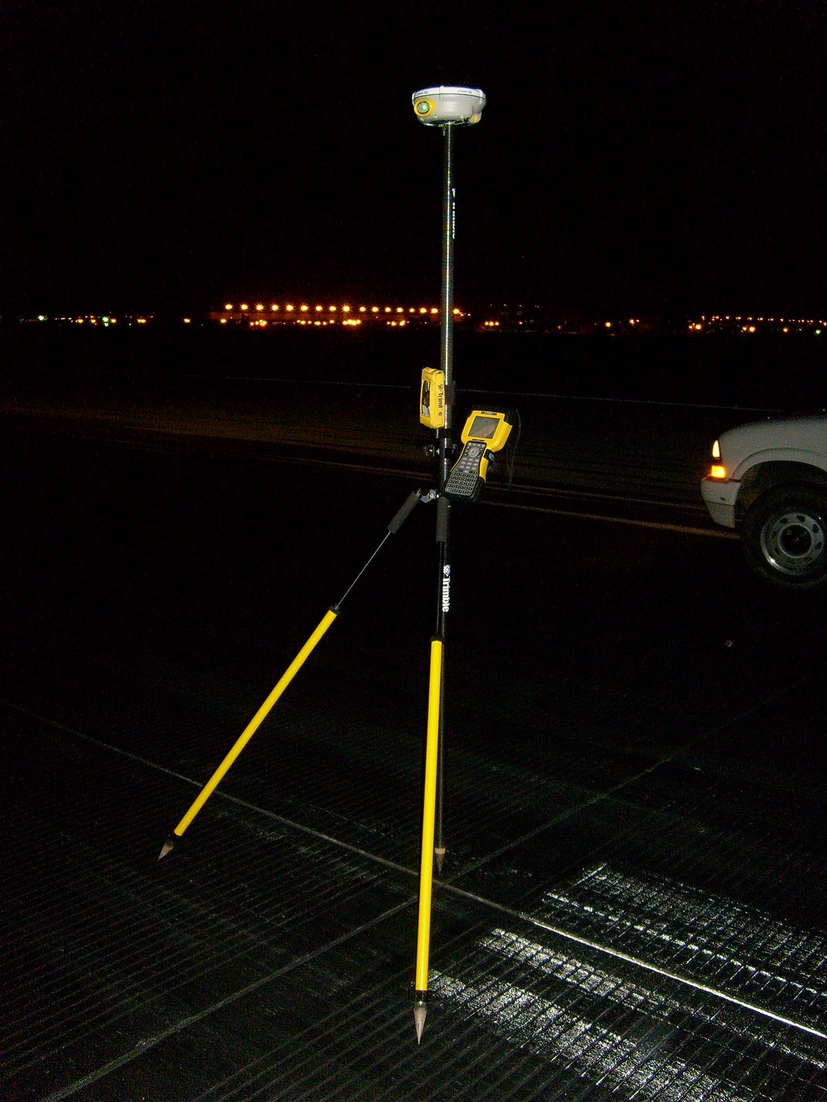
A GPS-based surveying system.  This unit is capable of accuracies
of +/- 4 cm within 5 seconds of being placed over a point.
How big is 4 cm?  About the size of a poker chip.
Not for the faint of heart, though.  The saucer-shaped thing at the
top of the pole (Trimble R8) is the high accuracy
GPS receiver and it alone costs about $8,000
____________________________________________________________
OK, back to our original topic.
The goal is to find a GPS receiver that:
a. comes in at around the $250 – $300 price point
b. can use our custom coordinate system
c. can use a high resolution aerial imagery as a background map
d. is easy to use – should be almost a ‘grab-n-go’ device
e. collects simple data points, lines or polygons in a format we can easily bring in to our GIS and CAD systems

We selected a fair number of units to test – the Magellan 315 and Thales MobileMapper mentioned earlier, a Trimble Juno and Yuma, a Magellan eXplorist 610, a DeLorme PN-60 and a Garmin eTrex 20.

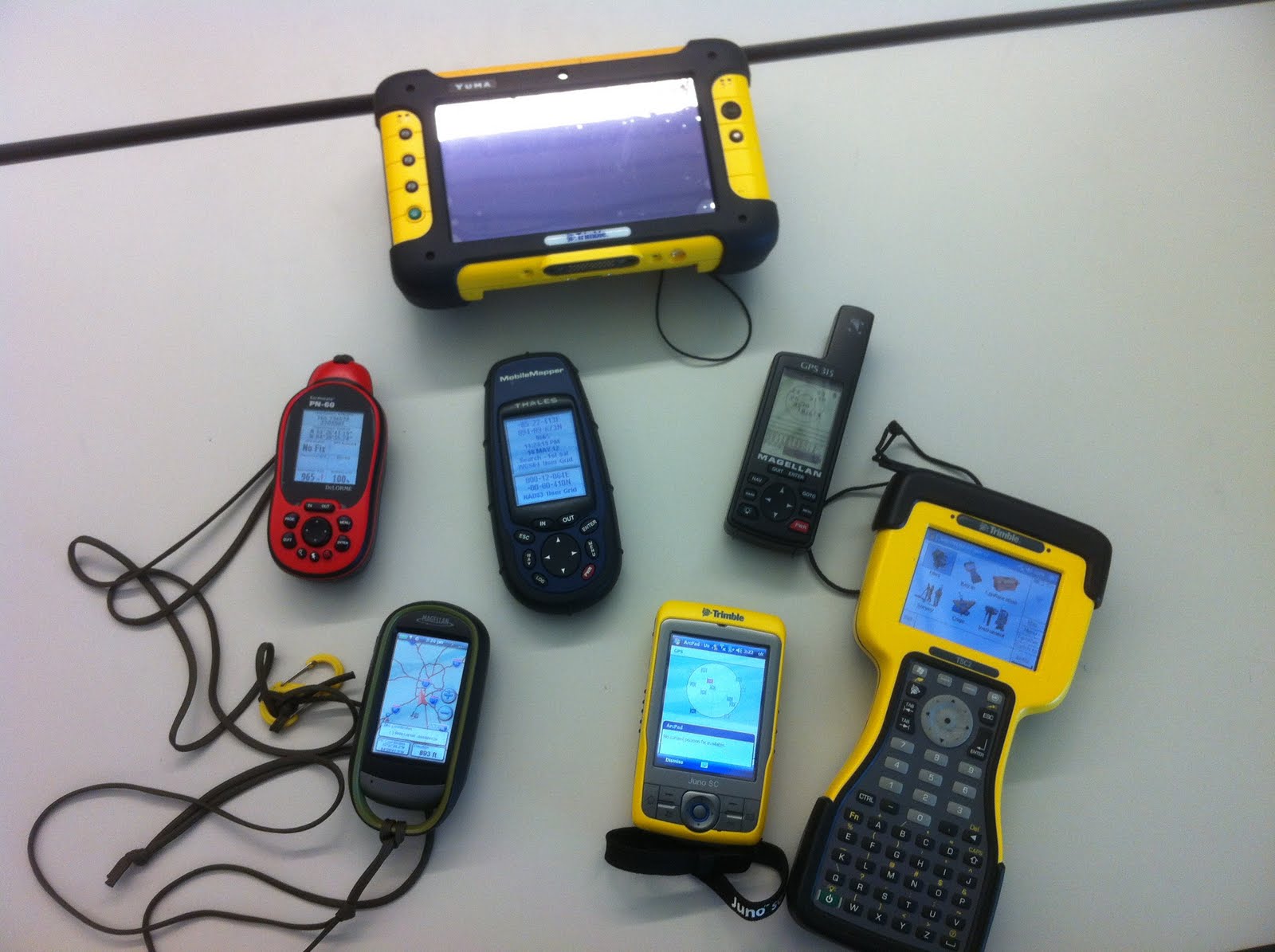
Top – Trimble Yuma
Middle – DeLorme PN-60, Thales MobileMapper, Magellan 315
Bottom – Magellan eXplorist 610, Trimble Juno, Trimble TSC-2

The DeLorme and the eTrex quickly fell out of the competition.  The DeLorme does not support user coordinate systems (a very disappointing shortcoming in an otherwise outstanding GPS unit).  The eTrex does have a user coordinate system setting, but it only works in meters (our custom airport coordinate system is set up in feet).  I was really pulling for the eTrex 20 because it’s the cheapest of our test samples ($175 Amazon price), has a good screen, an intuitive menu system and its receiver tracks both the US GPS and the Russian GLONASS satellites.  Alas, Garmin tech support could never figure out how to get it to provide readouts in feet so back to the store it went.

The Trimble Yuma is really a tablet computer running Windows 7.  It is a very capable device, but at the $5,000 price point falls way outside of our test objectives.

The Trimble Juno is an interesting unit.  It is essentially a highly customized PDA that runs Windows Mobile 6.1.  This Juno is really the lowest entry point in terms of price and features for a serious handheld GPS mapping and field data collection device.  Unfortunately the entry price is still too steep for this test – the hardware itself costs around $1,000 and the software needed to do field reconnaissance and data collection – ESRI’s ArcPad – runs an additional $400.  A good device, just too expensive and too complex for the non-technical user.

The Trimble TSC-2 seen in the picture above is not really a GPS receiver.  It is a survey-grade data collector that pairs with a high precision GPS receiver via Bluetooth (we use a Trimble R8) .  I threw it into the picture just for comparison.

The Magellan 610 pulled ahead early in the competition.  It’s a mid-sized unit that’s a bit chunky but fits well in the hand.  It uses a touch screen interface and it includes a 3.2 mp camera that geotags each image.  After some fiddling it took our custom coordinate system and returns very good accuracies on the order of +/- 10 ft.   I should mention that a large airport is an ideal location to test potential GPS accuracy since you have open skies horizon-to-horizon.  If the GPS satellite is above the horizon your receiver will see it.  No trees, buildings, towers, etc. in the way.  So please, don’t take my accuracy results as gospel.  Your real world results will vary.

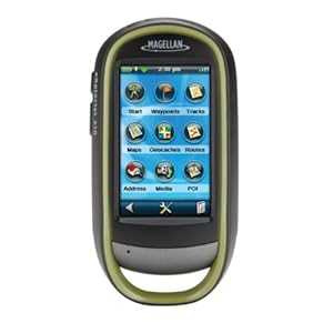
Magellan eXplorist 610
A very capable little device

Where the Magellan 610 stumbles is ease of use.  It has a lot of features – GPS, camera, compass, barometer and altimeter.  It is a jack of all trades and, to be honest, most features are fairly well integrated.  However, learning to use them takes time and it’s easy to get lost in the touchscreen menu system.  The Magellan also suffers from a disease that afflicts most other consumer grade handheld GPS units – ‘gamesmanship’.  In an effort to attract new customers manufacturers like Magellan, Garmin and DeLorme have built their user interfaces around the game or sport of geocaching.  It’s a fun game and a great way to get tech savvy kids off their asses and into the outdoors.  The low end GPS manufacturers see this as a market niche they can exploit and have structured most of their unit’s features around geocaching.

The problem we face is that geocaching-oriented GPS units makes lousy general purpose or field data collection units.  By focusing on geocaching the manufacturers have ignored the needs of a whole different market segment – the map data developer.

A weak coordinate system library, the lack of a GIS-industry standard vector data format such as the ESRI shapefile, weak data attribution tools on the GPS unit and a weak desktop mapping interface all hinder the use of these units as data collectors.  DeLorme comes the closest with it’s XMap desktop GIS software, but the cost is over $800 per license it continues to use a proprietary vector data format linked back to the PN-series receivers.

What the industry needs is a low-end map data collector that has a simplified interface optimized for adding and attributing data collected in the field.  It needs to use industry standard vector and raster data formats and should come with a more robust desktop mapping interface oriented towards the field mapping industry or enthusiast.  Magellan seems to be dipping its big toe back into this market with the Magellan eXplorist Pro 10, but this device still requires a third party software package like ArcPad and offers no improved desktop mapping software.

Magellan eXplorist Pro 10
This is just a re-packaged Magellan 610, but a good start!

So GIS industry wonks, here’s what I want:

1. a handheld GPS unit with a large, high resolution screen that is easy to read in broad daylight

2. consumer-grade accuracy using WAAS correction

3. a user interface highly optimized for field data collection – no third party software requirements!

4. a robust horizontal and vertical coordinate system library and the ability to accurately define a user coordinate system

5. a 5 megapixel digital camera with flash

6. the ability to configure field collection jobs or scenarios and save them as project files

7. twelve hour continuous use battery life

8. an external antenna port

9. fully waterproof

10. improved desktop software for device configuration and data download and upload

11. use of industry standard vector and raster data formats

And I want this all at a $700 retail price point.

So get to work.  I expect some nice surprises in your 2013 lineups!

– Brian

History Revealed! Origins Of The Army Lensatic Compass

For several years I’ve been trying to piece together the history of the US Army’s lensatic compass.  In an earlier post on this blog we discussed the various types of compasses and a bit of the developmental history that can be inferred by viewing the examples in my collection.  However, there was (and still is) very little solid history on the development of the lensatic compass available on the web.

For an item as ubiquitous as this compass the lack of historical data seems a odd.  The development and usage histories of many other items of WWII-era equipment are well documented.  Take the M1 Garand for example.  Collectors can discuss in detail every single part on that rifle and can accurately date and discern the manufacturer of each part by noting subtle differences in how the piece was machined or finished.  This wealth of knowledge is due to the fact that the development and production records for the Garand were made available decades ago by the US military and the various manufacturers.  Of course collector interest is also a factor.  The Garand is one of the most collected pieces of WWII equipment and when you have thousands of collectors clamoring for detailed information the odds are pretty good someone is going to unearth the data.  Since there can’t be more than a dozen serious collectors of Army lensatic compasses there’s a whole lot less clamoring.

As an item of individual equipment that guided millions of Soldiers across the battlefields of Europe and the Pacific in WWII, and continues in use by our Soldiers today, I’ve always felt the history of the lensatic compass deserved better coverage.

Earlier this week I was on a different quest.  I recently purchased an interesting bit of Army topographic kit, a Vertical Sketchmaster (I’ll do a posting on that later).  Since the device came without paperwork or documentation the first thing I did was hit Google for a quick search.

[A short segue here.  Hey Google, your search results are starting to look like those from the half dozen or so search engines that have all but fallen off the internet.  When I do a search on your site I’m looking for real results, not page after page of ads or eBay listings.  Any more, searching on Google is like searching on – dare I say it – Yahoo!]

Buried about three pages deep in the search results was a reference to a holding in the Defense Technical Information Center (DTIC) titled “History of [the] U.S. Army Topographic Laboratories (1920 to 1973)”.

The phrase “Army Engineer Topographic Laboratories” got my immediate attention because the document could only be referring to what used to be know as the Army Corps of Engineers’ Engineer Topographic Laboratories, or ETL.  ETL and it’s predecessor organizations within the Corps of Engineers served (and still serve) as the Army’s R&D lab for development of topographic, terrain analysis and geospatial systems, processes and equipment.  Now called the Army Geospatial Center, it was an organization I called on many times during my career for support and advice, and they always came through.

As luck would have it the document is available in digital form through Google.  I immediately downloaded it and started reading.  Published in 1973 as an ETL internal paper by John Pennington, it is a short rundown of the history of the Army’s topographic R&D labs and covers major projects and equipment development between 1920 and 1970.  I don’t want to spend too much time on this document in this post, because I feel it deserves it’s own separate discussion at a later date.  For now I’ll just say it is a treasure trove of historical information.

While reviewing the document for information on the vertical sketchmaster I quickly came across discussion of lensatic compasses.  This was something completely unexpected.  I never considered that the development of the lensatic compass was something an Engineer topographic R&D lab would have been involved with.  After reading the entries it now makes perfect sense – the Engineers had doctrinal responsibility for development of land navigation equipment and were the Army’s subject matter experts on compasses of all types.  While the development of land navigation techniques including the use of map and compass was the responsibility of the Infantry School, development of the compass as an item of equipment was the responsibility of the Engineers.  Of course the two branches worked hand-in-hand on the project, with the Engineers serving as a test and development agency in support of the Infantry School.

The document briefly discusses compass development both prior to and after WWII and adds some fascinating tidbits to the history of the development the lensatic compass:

Since the quality of the scan is pretty poor I’ve reproduced the key parts below:

(7)  Compasses.  Although the compass is not strictly a surveying instrument, considerable effort was expended by the Mapping Branch of the Engineer Board in the World War II period on the development of small compasses for Infantry and other arms.


The work started in 1938 when the Infantry requested that an inexpensive, commercial-type compass be found to replace the marching compass then issued because the marching compass was too large, elaborate, and costly.  This investigation was assigned to the Engineer Board, and it was soon found that no suitable commercial compass was available.  The W. & L.E. Gurley and the Taylor Instrument Companies, however, were willing to make a suitable compass based on a new design; and each company made six samples in 1939 as ordered from the Engineer Board.


After testing by both the Infantry and Cavalry and some modifications by the manufacturers, in November 1940 the Engineer Board recommended procurement of the cheap lensatic compass from both manufacturers.”


Thus we have the WWII-era M1938 lensatic compass.

M1938 Lensatic Compass
My question now is, was this originally a liquid filled model?  Read below.

One interesting point is that while lensatic compasses made by Gurley are fairly common (they were a major manufacturer of surveying equipment at the time) I have never seen a military lensatic compass made by Taylor Instruments.  However, Taylor Instruments did go on to be a major manufacturer of wrist compasses for the US military in WWII.

But the story is not over.  Even back in 1940 they were struggling with the issue of how to dampen the compass needle or card.

“Since the mechanical dampening arrangements in all compasses available up to that time had not been entirely satisfactory, the Engineer Board started investigations of liquid dampening in December 1941.  Compasses of both the lensatic and the wrist type with liquid dampening were developed, tested, and adopted in the 1941 to 1944 period; and it was thought for a time that the compass problem had been solved.  However, it was discovered that, with temperature changes, an air bubble often developed in the compass capsule which impeded the free movement of the compass needle and affected the accuracy.


In July 1944, the Superior Magneto Corporation, one of the liquid-filled compass suppliers, solved the liquid  dampening problem by applying the induction dampening principle.  The compass body was made of copper which set up an eddy current and magnetic field as the compass needle rotated, thus acting as a drag to dampen the needle oscillation.  Samples were immediately procured and tested.  As a result, the induction dampened wrist compass was standardized in April 1945, and the induction dampened lensatic compass was standardized in May 1945.”


Based on the number of WWII compasses available for sale from auction sites like eBay I think that Superior Magneto was the #1 supplier of lensatic compasses during WWII.  Knowing their core business – the production of magnetos – it makes sense that their engineers would have a clear understanding of the principle of induction and how to apply it to the problem of compass needle dampening.

Today M1938 compasses with induction dampening are easy to identify.  They have a white compass bowl that contains the compass card.  The white bowl is the stamped copper cup that the compass magnet interacts with to slow oscillation.  It is an excellent dampening system and is still used today in US military-issue lensatic compasses.

M1938 Lensatic Compass with induction dampening.
Note the white compass bowl.  This is really a stamped copper cup that interacts
with the north-seeking magnet to reduce oscillation of the compass card.

Let’s skip forward now to the late 1940s, when it was clear that the lensatic compass was in need of an upgrade.

(3)  Compasses.  The development of compasses, both the wrist and the lensatic types, was reopened in 1947 to provide instruments which would overcome the deficiencies noted in those developed during World War II.  Experimental models of the lensatic compass were produced by Taylor Instrument Company, Rochester, New York (Fig. 84), and the Brunson Instrument Company, Kansas City, Missouri.  Both were found to conform to the military characteristics, but the Brunson model was considered superior.  Experimental models of the wrist compass were produced by the Brunson Instrument Company, Kansas City, Missouri (Fig. 85), and were delivered to ERDL in January 1950.  Cold weather tests of the lensatic compass were conducted at Fort Churchill, Canada, and in January 1951 service test models were procured and shipped to service test agencies.  Here again, as with the compass development during World War II, emergency procurement of large quantities of both compasses were made before all testing and development had been completed.


Development of both compasses was completed in 1952.  The lensatic compass was classified as standard type, and the project was closed in November 1952.”


The result of these tests and type classification are the classic M1950 Lensatic Compass, a design still in use today:

M1950 Lensatic Compass produced in 2010 by Cammenga.
Today Cammenga is the sole contractor producing lensatic compasses
for the US military.

The M1950 is still one of the best compasses ever developed, and I consider it the best military compass ever issued to any military anywhere in the world.

The Military Lensatic Compass

I’m going to kick off our formal evaluation of compass accuracy with the a design that has been in continuous use  for over 60 years and has seen use by millions of individuals.  It is perhaps the most tested compass design in history, with documented use in jungle, desert, woodland and arctic environments around the world.  It is tried and true and is one of my favorite compass designs.

It is the US Army’s Model 1950 lensatic compass.

The M1950 compass is a design born of war.  It’s predecessor, the M1938 lensatic compass, was developed and adopted just as WWII opened.  It was a good design that was easy to manufacture.  Equally important, the adoption of the M1938 compass allowed the Army to standardize land navigation training, simplify it and teach it to the millions of young men who were being drafted into the Army and Marines. The experiences of war taught the Army a few things about compass design.  First, it proved that the lensatic compass design was a good one.  It was accurate, reliable and versatile.  With its compass card graduated in both degrees and mils it was usable by the both infantry and artillery.  The military liked the basic design and stuck with it.

A Model 1938 (M1938) lensatic compass manufactured
by the Superior Magneto Company of New York
Superior Magneto appears to have been the prime supplier of this
compass design during WWII

However, wartime experience also highlighted some shortcomings in the M1938 design.  It was somewhat fragile.  While not a toy, the M1938 was lightly built – just two stamped aluminum cups fitted together to form the compass bowl and lid.  It had no mechanism to lift the compass card off of the the pivot needle when the compass was closed.  A lot of compasses were damaged when the the tip of the pivot needle gouged or cracked the pivot jewel through rough handling.  But perhaps the biggest shortcoming of the M1938 compass is that it had no dampening mechanism. This meant that the compass card would swing wildly and would take a good number of seconds to settle down to the point where the Soldier could get an accurate reading.  There were some versions of the M1938, those manufactured by the W. E. Gurley Company (a leading manufacturer of surveying instruments), that included a needle lift mechanism that with practice could be used to brake or slow the compass card oscillations.  However, the vast majority of compasses were manufactured by the Superior Magneto Corporation and did not include this needle lift mechanism.

After WWII the Army incorporated induction dampening into the M1938 design.  Induction dampening is a beautifully simple concept.  It takes advantage of the inductive magnetic field generated between a swinging compass needle and a highly conductive but non-magnetic alloy like copper.  When a magnetic needle (or bar) is placed inside a cup made of copper and the needle swings (oscillates) that movement causes a slight magnetic eddy current to form.  When the needle swings to the left the eddy current pulls it to the right.  When it swings to the right the eddy current pulls it to the left.  The eddy current is self-canceling; as the needle oscillations decrease the eddy current strength decreases and very quickly the needle settles down and is aligned with magnetic north.  Simple, elegant and effective.

A late model M1938 compass with induction dampening.  This is
a transitional design, bridging the gap between the original M1938 compass
and the the M1950.  The white colored compass bowl is actually
a copper cup that forms part of the induction dampening system.
This compass was made in December 1950 by the
Marine Compass Company out of Pembroke, Massachusetts.

However, by the late 1940s the Army decided it was time for a whole new design.  The Army took the best functional elements of the M1938 compass – the lensatic sighting design and the combined degree and mil scales on the compass card – added induction dampening, a needle lift device, a much larger sighting lens and a larger thumb loop and placed it all in a beefed-up waterproof aluminum housing.  The resulting compass was designated the M1950 Lensatic Compass.  It is a rugged, versatile device that has remained in use with the US military for over 60 years, pretty much as originally designed.

M1950 Lensatic Compass
This particular compass was manufactured in February1953 by the
Marine Compass Company out of Pembroke, Massachusetts.   The
cloudy dial cover is the result of the plastic aging.  Remember, this compass
is almost 60 years old!
Same compass with the cover closed, showing the manufacturer and
manufacturing date.

Fast forward almost 60 years and the same compass design is still in use by the US military, and it doesn’t look like they have plans to switch designs any time soon.

M1950 Lensatic Compass manufactured in 2010 by the Cammenga Corporation
out of Michigan.  This is a military issue compass that uses tritium inserts
for night time illumination.
The same compass with the cover closed.  At the time of this writing
Cammenga has been the sole supplier of lensatic compasses to
the US military for over 10 years.

Since 1950 this compass has been produced by a number of manufacturers, including the Marine Compass Company, Jay-Bee, Union Instrument, Cammenga and even Lionel (yes, the train people!).  However, it seems that the single biggest manufacturer of M1950 compasses was Stocker & Yale out of Massachusetts.  I don’t have any specific production numbers for these compass manufacturers so my claim is based solely on personal observation.  Based on the compasses I was issued in the Army and what I see for sale on auction sites or in surplus stores it appears that Stocker & Yale had the highest production numbers.

Now, the US military doesn’t just turn to a manufacturer and say “Make it!”  Like all things military there are clearly defined specifications.  It doesn’t matter if you are building an aircraft carrier or a handheld compass, there must be clearly spelled out specifications!  So it is with the M1950 Lensatic Compass.  Today’s compasses are built and tested in accordance with the DOD military performance specification known as MIL-PRF-10436N (Performance Specification, Compass, Magnetic, Unmounted, Lensatic, Luminous, 5 Degree and 20 Mil Graduations, With Carrying Case).

MIL-PRF_10436N
The document that spells out the design, construction,
performance and testing requirements for the
lensatic compass

(I should note here that the current specification does not use the ‘M1950’ designation.  I’m not sure when the US military dropped the designation, but for our purposes we’ll continue to call it the M1950.  It’s the same compass.)

The discussion of this performance document is important because the M1950 compass is the only US produced handheld compass I am aware of that is built to a specific performance specification, and is regularly evaluated against this performance specification by an outside agency.  If any test batch of compasses fails the evaluation the devices never make it out of the factory.  The M1950 is a purpose-built device designed to meet a clearly laid out specification not just for accuracy but for shock resistance, water resistance, illumination, thermal shock, durability and service life.  Manufacturers of other compasses may have their own internal standards (and many are quite good), but the M1950 is the only handheld compass you can buy that is designed to meet demanding military standards and is rigorously tested by an independent agency to ensure it meets those standards.

So just how good is the M1950 compass in the real world?  Pretty damned good!  The 58-year old example I show above that was made by the Marine Compass Co. is still perfectly serviceable and would probably meet all of today’s performance specifications for accuracy and durability.  I have other examples in my collection that have clearly seen hard use, some with broken components or cracked dials, but they still provide reliable and accurate readings. The M1950 compass is a device that is hard to kill.

I believe that the key to the M1950’s ruggedness is the fact that is it not a liquid dampened design.  Liquid dampening (where the compass needle or card is suspended in fluid to reduce oscillation) is very effective but is a more fragile design than the induction dampening used in the M1950.  With the liquid filled design the compass needle or card must be sealed inside a leak proof capsule*.  The problem is, compass manufacturers have not yet figured out how to make a leak proof capsule.  I have over 15 liquid filled compasses in my personal collection.  About half have air bubbles inside the capsule, a sure indicator that the fluid is leaking.

How accurate is the M1950 compass?  Every M1950 I’ve used (and after a 23 year Army career I’ve used a lot of them) has at least met, and many exceeded, the performance specification for accuracy.  Now this is where I need to come clean on my evaluation of the M1950.  It is not the most precise handheld compass available.  This compass’ biggest design limitation is that the compass card is divided into only 5 degree increments; pretty coarse even for handheld use.

Compass card of the M1950 compass.
Note the inner degree ring (in red) laid out in 5 degree increments.  The outer
ring (in black) is set out on mils (6400 mils to a circle).

This means that the average user, the common Soldier, can only discern and measure to half of that increment – 2.5 degrees.  Experienced users – mostly infantry and artillery Soldiers who use a compass regularly – can frequently get accurate readings to between 1.5 – 2.0 degrees. But to be realistic, 2.5 degrees is about as good as anyone can expect to get with this compass card layout.  The M1950 compass card design is a compromise.  The military needed to include a mils scale for use by the Field Artillery.  Mils offer more discreet division of the circle (a mil is 1/6400th of a circle), allowing for more precise azimuth determination – very important when you are calling in artillery strikes on distant targets.  To accommodate the mils scale it needed to be printed at the outer edge of the compass card, leaving less space to print the degrees scale.  This results in a coarse, less precise degree scale.

The military performance specification states that the compass must be accurate to within 40 mils.

“4.4.1.8 Magnetic performance and compass error.  The compass shall be placed in a horizontal position on a fixed point and by means of the sighting mechanism, the compass shall be sighted on three targets of known magnetic azimuths approximately 120 degrees apart.  With no remedial action by the operator, before, at, or after, a reading shall be taken at each target.  The difference between the known azimuths and readings taken is the compass error.  An error greater than 40 mils or failure of the compass to function correctly shall constitute failure of this test.”

Since one degree = 17.8 mils, 40 mils is slightly less than 2.5 degrees.  Let’s round up and call it 2.5.

I have tested my 2010 production Cammenga compass at a known azimuth station and found it to be accurate to just over 2 degrees when used in the handheld mode and sighting on targets up to 150 feet away.  This compass very easily meets the performance specification.

Before I wrap up this blog post I need to add that the M1950 compass was merely one component of a land navigation system that the Army developed and adopted at the end of WWII.  Along with the M1950 compass came dramatic changes in how the Army mapped the world, developing standardized maps with overprinted grids (the Military Grid Reference System) and plotting tools.  It was all designed to simplify land navigation for the common Soldier, and is was so successful that the methodology is still in use today.

The US Army’s standardized land navigation ‘system’ included the M1950 compass,
standardized topographic maps, plotting tools and training materials.  It was an
extraordinarily successful program that is still used today.

Let’s wrap this up.  Here is my bottom line – I consider the the M1950 compass to be the best general purpose handheld compass available.  It is a proven design that is built and tested to exacting standards.  They are readily available new or used to civilians and are one of the best examples of trickle-down military technology I’ve seen.  If you spend any time in the outdoors you need a compass.  You might as well get the best available.  Get a M1950 Lensatic Compass.

Thanks!

– Brian

*One compass manufacturer, K&R out of Germany, claims to make a leak proof liquid capsule but I don’t think they have been on the market long enough to have proven the claim.

The Pocket Transit

In Which Way North? (Part I) we discussed the history of the magnetic compass and talked a bit about magnetic declination.  Now let’s start looking at some specific compass designs and discuss why they were important.

To start we’ll look at a compass design that is uniquely American and was born of the late 19th Century explosion of mining and mineral exploration in the US.  This compass was originally conceived to fit a very specific need, but it was so well designed and executed that it found use in a wide variety of applications and industries.  It continues to be produced today, over 100 years since its introduction and little changed from its original design.

The Brunton Pocket Transit was patented in 1894 by David Brunton, a Colorado mining engineer.  Brunton was frustrated by the number of survey instruments a mining engineer and geologist had to carry around with him (and I say ‘him’ because mining engineering and field geology was an exclusively male profession well into the 20th Century).  In the late 1800s it was not unusual for engineers and geologists doing basic exploratory mineral mapping to lug around full sized survey transits, surveying compasses, tripods, clinometers, and plane tables. These instruments offered a high level of accuracy that simply wasn’t needed for exploratory surveys.  As an engineer himself Brunton realized that what was needed a portable device that allowed field survey personnel to do fast and accurate exploratory quality surveys without being burdened down by equipment that was heavy, expensive and difficult to set up and use.  These men were in the business of discovering, verifying and mapping mineral deposits that covered vast areas.  Huge sums of money were at stake as mining and mineral companies scrambled to secure valuable leases on the stuff that was fueling America’s exploding industrial economy – timber, gold, silver, coal, iron ore, chromium, nickel, bauxite, petroleum and dozens of other minerals that were key to America’s growth.  Field engineers and geologists needed to move fast, do rough mapping and get that information back to the office for the development of lease maps and boundary descriptions.  They didn’t need to be burdened with heavy, sensitive and fragile survey gear if that level of accuracy wasn’t required.  David Brunton recognized the problem and set to work developing a solution.

What Brunton came up with as a pocket-sized device that incorporated an accurate magnetic compass with a sighting vane, a clinometer, a level and a large mirror with a sight line.  Housed in a machined aluminum case (still an expensive material in the late 1800s), it was rugged, reliable and useful.

Brunton named his instrument the ‘Pocket Transit’, a lofty title for a fairly rudimentary mapping device.  But the name served its intended purpose; in the mind of the engineer and geologist it set the device apart from the common handheld compass.  Here was a professional instrument that offered a level of accuracy and functionality not found elsewhere.

Brunton’s 1894 model Pocket Transit

Brunton had more than marketing on his side.  The Pocket Transit actually delivered where it mattered – in the field and in the hands of engineers and geologists across North America.  It delivered all the functionality and accuracy needed to get the job done.  It ended up being the perfect device for the job at hand.

Demand for Brunton’s device increased steadily and improvements were introduced.  An additional bubble level and a cover mounted peep sight were added in 1912.  In the same year Brunton introduced modifications to the case that allowed mounting the instrument on a non-magnetic tripod or jacobs staff.  (It’s interesting that in his 1894 patent application Brunton derided other compass designs that needed to be tripod mounted, but in the 1912 patent application he discusses tripod mounting like it’s the greatest idea since sliced bread.)  Somewhere between 1894 and 1912 the Pocket Transit acquired the ability to pre-set magnetic declination by use of an adjustment screw on the side of the case.  By 1926 Brunton’s design had fully matured with the addition of a bullseye level for improved leveling and the addition a percent grade scale to the clinometer.  From this point forward it was minor improvements in materials, manufacturing techniques and the added availability of different compass ring layouts (degrees, quadrants, mils, etc.)

A 1926 patent model of the Brunton  Pocket Transit.
Note the round level and the percent grade indices
at the bottom of the clinometer scale.  This is the basic
design still in production today.
One of the reasons Brunton’s pocket transit was
so damned useful is that he made it a complete package.
Early in the production of the pocket transit Brunton started
engraving sine and tangent tables on the lid.  Using these
tables in conjunction with the clinometer an engineer could
quickly and accurately determine heights of objects like trees
or cliff faces.  To this day Brunton includes the sine and
tangent tables on the lids of all pocket transits.
So damned useful!
From the beginning David Brunton licensed the Colorado instrument maker William Ainsworth & Sons to produce the pocket transit.  After Brunton’s death in 1927 Ainsworth purchased the manufacturing rights to Brunton’s designs and continued manufacturing and improving the Pocket Transit through the late 1960s.  In 1972 the production rights and the Brunton name were purchased by the Brunton Company of Riverton, Wyoming.  The Brunton Company continues to manufacture this basic design.

The Brunton design was so well thought out that engineers and geologists quickly developed field techniques keyed to the Pocket Transit’s unique layout and construction.  The best example is the determination of the strike and dip of rock formations.  Most sedimentary and metamorphic rock formations are not horizontal.  They were all deposited in horizontal layers but over geological time (i.e., millions of years) those horizontal layers have been warped and deformed by pressure and other geological forces.  One of the keys to understanding these forces is mapping the strike (the horizontal angle of deformity) and dip (the vertical angle of deformity) of individual rock layers.  Before the Brunton Pocket Transit the measurement of strike and dip was a clumsy process involving two separate devices – a field compass (often a fairly large and somewhat fragile device) and a clinometer.  With the Brunton the process is quick and simple – open the instrument and lay it horizontally against the rock formation.  Keeping the edge of the instrument in contact with the rock face rotate it up and down slightly until the circular level is centered.  Note the magnetic azimuth as indicated by the compass needle.  That is your strike.  Score a line on the rock face horizontal to the pocket transit using a piece of chalk or small piece of rock and remove the pocket transit.  Make another score mark that is perpendicular to the horizontal mark you just made (your mark should look like a ‘T’).  Place the Pocket Transit along this perpendicular mark and measure the angle of slope using the built in clinometer.  This is your dip.  It takes longer to describe than it does to do it in the field.  This is the standard measurement technique for strike and dip, and every college and university geology department in North America teaches it as part of their field geology curriculum.

From the University of Calgary website.  Measuring the strike
of a rock formation using a Brunton Pocket Transit.
From the University of Calgary website.  Measuring the dip of
a rock formation using the Brunton Pocket Transit.
My introduction to the Brunton Pocket Transit came in the mid-1970s while studying geology in college.  We learned strike and dip measurement techniques early on in the field methods class, and later during our summer field geology course we ranged across the southwestern United States, making thousands of strike and dip measurements in an effort to understand the geologic processes that formed the unique landscape of that region.  I saw the Pocket Transit as a useful but fairly limited device, suited only to the field geologist.  Years later while attending a course at the Defense Mapping School at Fort Belvior, Virginia, our class got an intensive block of instruction on the use of the Pocket Transit not just for strike and dip measurement but for height determination, precise azimuth determination, basic plane table survey work and rough site layout.  I finally saw the full potential of the Pocket Transit and purchased my first one soon after.  That Pocket Transit has seen service in Kuwait, Honduras, Panama, Germany, Bosnia, Korea and across the US.  It has been a constant companion on hundreds of field surveys, assisting with tasks like mapping out refugee camps on the Empire Range area of the Panama Canal Zone, measuring road grades along the Pan-American Highway in Honduras and fixing North Korean observation point locations along the Korean DMZ.

The Brunton Pocket Transit doesn’t measure horizontal angles as well as a conventional transit, it doesn’t measure vertical angles angles as well as a theodolite, sextant or even an Abney hand level.  If you need to shoot azimuths using handheld techniques the Army lensatic compass is a better tool.  However, the Pocket Transit does all of these tasks well enough, and puts everything needed into a compact, easy to carry package that really does fit into your pocket.  (In his patent application David Brunton noted that the instrument fits nicely into a vest pocket – therefore the name pocket transit).

Let’s have a look at some Brunton Pocket Transit variations (click on the pictures for an enlarged view):

This is a modern incarnation of the Pocket Transit – a glass filled composite
body version.  This particular Pocket Transit is almost 20 years old
and has been used around the world, and it still looks new.
This is a particularly nice WWII era Pocket Transit manufactured in 1943.
This model is graduated in mils (6400 mils in a circle).  Designated the
M-2 Compass, it was designed for use by artillery troops who need a more
discreet subdivision of the circle for accurate artillery gun laying and spotting.
A variation of this model is still used by the US Army and USMC today.
An early induction dampened model graduated in degrees
A nice post-war model graduated in quadrants instead of degrees.
Most early Pocket Transits were sold with the quadrant setup rather than
degrees.  The use of quadrants was the accepted method of noting direction
within the engineering and geology community up through the 1970s.  Brunton
still sells a modern version of this layout, but it really is useless for general
navigation purposes.  If you want to do land navigation with a Pocket
Transit get the model laid out in degrees!

As you can tell, I think the Brunton Pocket Transit is a nifty little tool.  But it is not a novelty, not something to be put on a shelf to be admired.  The Pocket Transit is designed and built to be used.  It represents American ingenuity at its best.  From 1894 on the Pocket Transit ended up being used in all corners of the United States, doing useful, often rough duty helping to map American and her natural resources.  Rugged, reliable, useful.  American to the core!

Brian

In writing this blog post I relied heavily on several sources that I feel need to be acknowledged.

First is William Hudson’s excellent website About Brunton Pocket Transits.  Mr. Hudson’s site is the most complete compilation of information about Pocket Transits on the web, and should be the starting point for anyone interested in finding out more about these great little devices.  Thanks you Mr. Hudson.

Next is Dr. Peter H. von Bitter’s article The Brunton Pocket Transit, A One Hundred Year Old North American Invention.  Originally written in 1995 for the journal of the History of the Earth Sciences Society to celebrate the 100 year anniversary of the invention of the Brunton Pocket Transit, von Bitter’s article forms an excellent short history of the man David Brunton and his famous invention.  Thank you Dr. von Bitter.

Although not source, there is an scanned copy of a 1913 Ainsworth bulletin available on the the Surveying Antiques website.  This bulletin describes the various ways to hold and use the Pocket Transit and is an interesting overview of the instrument and its uses.