Measuring Things

US Coast & Geodetic Survey leveling party working in Atlanta, 1927

In the olden days, like before GPS, before you could make an accurate map real men had to go out and measure things.  This ‘measuring’ was called surveying, and it involved the extremely precise and accurate determination of the horizontal and/or vertical location of points on the ground known as survey control.  This survey control establishes the accurate framework upon which a map is built.  Horizontal measuring was called triangulation. Vertical measuring was called leveling.

 
The picture above comes from the US Coast & Geodetic Survey 1927 Seasons Report prepared by Captain E. O. Heaton (USC&GS).  It shows a topographic leveling party at work in Atlanta.  If anyone can figure out where in Atlanta these guys are working I’d love to know!
A few things to note.  The fellow holding the umbrella is most likely a black local laborer hired to help the party haul equipment and provide general assistance.  The umbrella he’s holding isn’t to keep the surveyor from getting sunburned – it is to protect the instrument from direct sun and prevent glare when sighting through it.  To ensure accuracy survey parties often used umbrellas to shade their instruments and stabilize temperatures.
The fellow squatting is a surveyor who is acting as the recorder.  He is writing down the readings being called out by the surveyor looking through the instrument.  The recorder’s job was extremely important because he didn’t just write down what the surveyor called out, he would do on-the-fly quality control checks on the values the surveyor gave him to ensure they were staying within the accuracy standards established for that particular survey.  If the recorder makes a single mistake, such as not catching an error in the surveyor’s observations or by writing something down wrong (like inadvertently transposing a number or putting a decimal point in the wrong place) he could lose an entire day’s work.  In my experience you wanted your  most meticulous guy and your best mathematician doing this job – perfectionists made good recorders.  The recorder is writing his notes down in a bound hardback book known as a survey field notebook.  That notebook would be turned in to the USC&GS at the end of the project and go on to become a part of the legal record of the survey.  I have no doubt that very notebook still exists in the archives of the USC&GS now held by the National Oceanic and Atmospheric Administration.  I’d love to take a peek at it!

(The job of recorder is one of those skills that has been replaced by computers.  Today’s surveying instruments now automatically store the readings and calculate values internally.  The computer integrated into the survey level lets the surveyor know via a digital display if the readings are within the specifications set for the job.  It’s called digital leveling.)

But what is the surveyor looking at?  Well, there are two people missing from this photo that make up the leveling party.  The surveyor is looking through the survey level at a stadia rod being held by another party member known as a rod man.  A stadia rod is a long pole marked off in feet and inches.  Behind the surveyor is another rod man with another stadia pole (the location of the stadia poles is determined by the survey party chief and is based mainly on topography and the ability to see both poles from where the survey level is set up).  The surveyor looks though the level and calls out the elevation mark he sees on the first stadia rod.  He then reverses direction and calls out the elevation he views on the second stadia rod.  The difference in numeric values he views on the two stadia poles is the difference in elevation between them:
Click on the image to open full size
Additionally, if this is a simple differential leveling job (and I think it is based on the type of level being used), there is another crew of chain men measuring the distance between the two stadia rods.  In 1927 this would have been done using steel survey tapes or chains.
Leveling is slow, tedious and physically demanding work.  There were no old farts out working on leveling parties except perhaps as party chiefs.  The rod men and the chain men were constantly moving, carrying the survey forward.  The instrument man and the recorder were responsible for moving and setting up the level in a new location, and the party chief was moving between all members of the survey party and scouting ahead for new setup locations.
Their work was absolutely critical, though.  The meticulous work of the surveyors of the US Coast & Geodetic Survey and the US Geological Survey created the accurate spatial framework that this countries maps and charts continue to be built upon.
But that’s not the end of this story!  I got interested in this picture for a particular reason.  The vertical survey control for the airport I work at was established by this particular USC&GS survey project.  I would like to think that it was these three unnamed gentlemen who, sometime in 1927 or 28, ran their traverse down into College Park, GA and set the single elevation benchmark that became the origin point for all vertical survey work done at the airport until the advent of GPS-based survey in the late 1990s.
Brian

In Praise of the Old Topographer

Progress is good.

Without progress we wouldn’t have a lot of great things like:

Penicillin
Computers
Electronic ignition
Cell phones
Frozen pizza

Few could argue that these developments have significantly enriched our lives or made them easier.  (Have an issue with electronic ignition being on the list?  Ever hand crank a car to get it started?)

But too many people equate change with progress.  If you change something, particularly if you change something that few people really understand, you can claim progress and nobody really stops to say, “Uh, I don’t think so”.

So it is today with my ‘profession’ – Geospatial Information Services (GIS).

I put the term profession in quotes when using it in conjunction with GIS, because I’m not really sure GIS is a profession.  It certainly is a job – there are thousands of people working GIS jobs around the world, but in my opinion it’s not really a profession, not yet anyway.

And the story of GIS is the story of change without real progress.

Background.  I have been working in the mapping, survey and geographic analysis field almost continuously since 1980.  I watched as the US military, particularly the Army geospatial engineering field, transitioned from the old manual analysis and production methods to computer-based analysis and production.  When I started it was all hand drawn overlays and paper maps.  Today it is GIS software and web-based mapping services.  I have certainly seen change in my field – fundamental, earth shaking change.  I’m not so sure I’ve really seen a lot of progress.  In fact, I would claim we’ve actually moved backwards in our ability to provide clear analysis and decision support tools to our customers.  We have moved forward with change, yet backwards with progress.

How can that be?  Simple.  The GIS field has traded fundamental skills for computer application expertise,  and the lack of fundamental skills and the ability to do critical analysis makes the field a slave to the software.

Change without progress.

Go up to any GIS professional and ask him or her to describe their job.  They will stumble around trying to explain it to you and invariably the words ‘arcgis’, ‘computer’, ‘database’ and ‘web maps’ will leak out.  The GIS professionals today can not think about, describe or relate their jobs without first thinking about the computer application.  For far too many of them the computer application is their job.  Continue the line of questioning and ask them if they think they can continue to do their job effectively without their computers and GIS software, even for just a short period of time.  Again, most will say no – in their minds their ‘profession’ is inseparable from and defined by the software.

Ask a civil engineer to define his or her profession.  You won’t hear words like ‘autocad’ or ‘microstation’ slip out, yet AutoCAD and MicroStation are the two leading engineering design packages in use around the world.  Reason?  Civil engineers don’t define their profession in relation to software applications.  Civil engineers are educated and trained to solve complex issues using analytical skills.  I work every day with extremely competent civil engineers who plan and manage multi-million dollar projects, yet they don’t even know how to open up an AutoCAD drawing file on their desktop computer.  They were hired for their engineering and problem solving expertise.  Software applications are merely enabling technologies that allow them to work more efficiently.

Put the same question to a land surveyor.  You won’t hear terms like ‘terramodel’, ‘geomatics office’, or ‘civil3d’.  These are software packages that enable surveyors to do their jobs more effectively and efficiently, but they do not define the profession.  The survey profession is defined by a set of standards tied to analytical and problem solving skills.

In each of these cases the profession defined what it needed from the software and the vendors responded.  In the GIS field things evolved the other way.  In the beginning (way back in the 1970s), the term ‘GIS’ defined software, not a skill set (the original term GIS stood for ‘geographic information software’ and has only recently morphed into ‘geospatial information system’).  Other professions like Forestry, Geology and Geography started using GIS technology to better manage large amounts of data that had a spatial component – things like timber stands, mineral lease boundaries and census data.  The software was revolutionary, but it was an enabling technology and not an end in itself.  Because the software was used by a broad range of professions there was little standardization.

As the years progressed and GIS software matured, more and more individuals became captivated by the GIS concept.  I will admit, in addition to having powerful analytical capabilities GIS packages like ESRI’s ArcGIS are just plain fun to work with.  However, these applications do little to enforce standards.   Everybody gets to do what they want.  That’s not the software’s fault – it’s up to the GIS professional to apply recognized standards.  But before you can have standards you have to clearly define your profession, and if you can’t define your profession how can you define your standards?  It was as though GIS had no conceptual roots – a discipline born anew, without heritage or precedent.  And nobody wanted to take ownership.  So, heavy GIS software user self identified themselves as ‘professionals’ and happily motored along, defining themselves any way they wanted.  As a result the GIS profession has become a primordal soup of software users with varying skill sets.  Some are damned sharp, other’s have trouble finding the ArcGIS icon on their computer desktop.  Yet all get to claim the title of ‘GIS Professional’ because, well, nobody told ’em they can’t.*

I refuse to be defined by a software package.  I am better than that, and my employers didn’t hire me for my button pushing skills.  They hired me to solve complex problems and provide unique services no other group in the organization could provide.  If I can provide the answer by scribbling a few calculations on a notepad, great.  If I have to fire up high end GIS software to run a complex analysis, OK.  How I arrive at the solution is immaterial to my employer, they just want an accurate answer that conforms to the established standards of the disciplines I’m touching.

But if GIS is the software, what is the discipline?  What melds geography, geology, forestry, hydrology, landform analysis, civil and structural engineering, environmental science and surveying into a multi-discipline approach to problem solving?  What discipline applies the best approach to describing the land and the structures on it and features below it with accuracy and precision?  What discipline relates data using a multi-disciplinary approach to solve the unique and complex problems beyond the realm of other earth science and engineering disciplines?  That discipline doesn’t exist, you say?

Balderdash!

The discipline I describe has existed for over 150 years.  This discipline opened the American west to exploration and settlement, unlocked the vast natural resources of this country and helped fuel it’s rise to an economic world power, it charted America’s home waters for safe navigation, mapped vast expanses of Central and South America and even mapped the Moon to identify safe landing areas for our Apollo missions.  Most came to this discipline from other professions.  It drew in its share of civil engineers, geologists, surveyors and geographers.  It was once the leading career choice for the top graduates from West Point.  This discipline started to die out in the 1980s, with the rise of specialization and computerization, when we tried to replace broad experience with computer algorithms.  Yet it is a discipline that is still as relevant today as it was in the mid-1800s, perhaps even more so as our infrastructure, development, enviromental, and energy issues start to intersect in ways only spatially-based analysis can address.

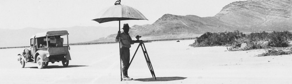
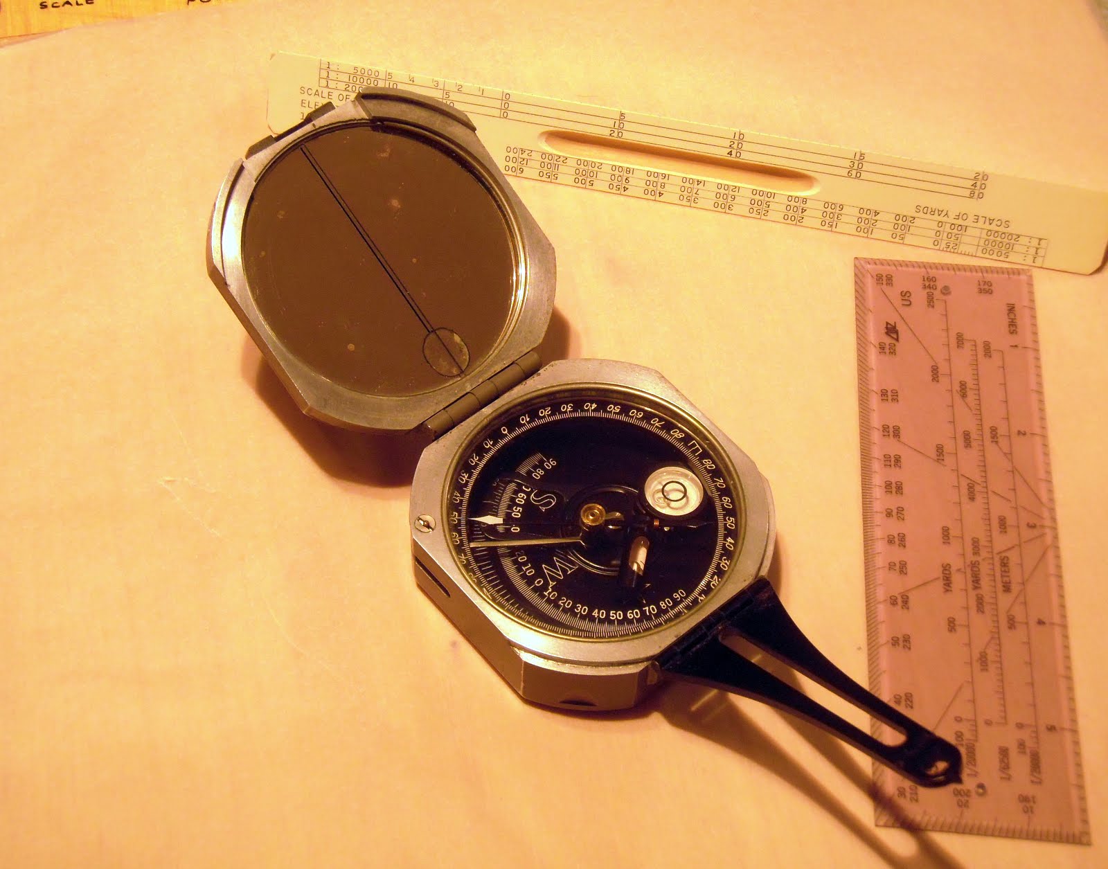
This is the discipline of the old Topographer!  

A topographer of the old Coast & Geodetic Survey, conducting
what is essentially a geospatial analysis using a plane table survey set

By definition, a topographer is someone who precisely maps and describes a portion of the earth’s surface and the man made features on it.  That is about as elegant a description of what I do as any I’ve found.

So, don’t call me a GIS professional, analyst, manager, coordinator or anything else related to a software application.

Call me a Topographer!

– Brian
* I understand we have this thing called the GISP certification program.  In its current form it’s a joke.  What does it certify?  Other professions with established licensing standards, like the engineering and survey fields laugh at the GISP certification program.  How can you certify against something that doesn’t have standards?

Right Under My Nose The Whole Time

As many of you know, I’ve been scratching around for some time trying to dig up the origins of the Military Grid Reference System (MGRS). I recently became interested in it in light of the fact that the US Geological Survey and Department of Homeland Security have adopted MGRS as the grid standard for the continental US (they’re only 60 years late, but who’s counting!).

I had some old friends at Fort Bragg who are involved in the mapping & charting field root around and they came back with the opinion that development of MGRS was likely tied to NATO and NATO standard agreements (STANAGs as we used to call them). There is probably some truth to that, but there were still several pieces of the puzzle missing. One of those was just when the US Army adopted MGRS.

For the past several months I’ve been scouring eBay, purchasing early copies of US Army map reading and land navigation manuals. The first official, general issue map reading manual came out in 1938 (Basic Field Manual Volume 1, Chapter 5, Map and Aerial Photograph Reading) and was quickly followed by updates in 1941 and 1944 as FM 21-25.

Tucked away in the back of my 1944 copy of FM 21-25, Elementary Map and Aerial Photograph Reading were two changes that I never paid much attention to. ‘Changes’ in Army parlance were updates to manuals or other documents. The Army would publish a change in the form of an addendum and distribute it throughout the Army. It was the individual unit’s job to make sure all the changes were ‘posted’ (this usually meant you physically attached the change document to the base document by some means, like stapling). That’s how the military managed publication changes before this internet thingey came along.

Today I was giving this manual a close read and decided to pay attention to the change documents. To my surprise one of the changes (Change 2) was dated November 1950 and was summarized as follows:

“Principal changes are in methods of giving grid references. These changes are made to comply with AGAO-S 061.3 (28 Dec 49) CSGID-M, dated 29 December 1949, which establishes the MILITARY GRID REFERENCE SYSTEM as official for the Department of the Army”

So there you have it. The Army adopted MGRS in December 1949. Part of the mystery solved!

So now I know the why and the when. What’s still missing is the how.

MGRS is based on the Universal Transverse Mercator Grid (UTM), which was developed by the Army Map Service sometime right after WWII.  What I need to find now is the original description of UTM and MGRS, the document prepared by the Army Map Service describing how MGRS is calculated and constructed, and how it should be implemented.

My guess is that these founding documents are buried deep in the archives of the National Geospatial-Intelligence Agency (the descendant of the Army Map Service).

Anybody know someone at NGA who can spend a lunch hour digging around for this info?

– Brian

Inter-American Geodetic Survey

The Inter-American Geodetic Survey (IAGS) was one of those extremely successful, yet little known, US Army (and later, Dept. of Defense) programs established after WWII.

The IAGS was created specifically to assist Latin American countries in surveying and mapping their vast internal regions that were either poorly mapped or entirely unmapped. The IAGS was established in 1946 as part of the Army Map Service and was headquartered at Fort Clayton in the Panama Canal Zone. The Army Map Service set up a complete survey, cartographic and map reproduction school at Fort Clayton and over the next 30 years trained thousands of military and civilian personnel from most Latin American and Caribbean countries. Attendance at the IAGS school at Fort Clayton was seen as right of passage for many up and coming officers in Latin American militaries, and it was common to run across senior officers – colonels and generals – from South American countries who talked fondly of their time spent at Fort Clayton, taking surveying or cartographic classes (one infamous graduate of the IAGS schools just happens to be Panamanian dictator Manuel Noriega, who attended the cartographic school in the 1960s).

The IAGS didn’t just provide training.  It also provided the equipment and personnel to assist the participating countries in establishing their own self-sufficient mapping and surveying programs.  The goal was to provide the training, equipment and technical support but have the individual countries take over their own mapping efforts.

Now, I’m not going to pretend that the IAGS was all altruistic good-will on America’s part.  We learned the hard way during WWII that many Latin American countries were at best reluctant allies, at worst active sympathizers with the Nazi regime.  At the end of WWII the political systems in these countries ranged from shaky democracies to hard line dictatorships.  The US Government became concerned about the effects of political unrest and Communist influence in the region, and instituted a number of programs designed to bring Latin America firmly under American influence and to foster democratic principles and improve economic conditions.  The IAGS was just one of many programs created as part of this effort.  One extremely important benefit the IAGS provided back to the US was that we were able to get American personnel on the ground in these countries to make detailed evaluations of local conditions (after all, that’s what surveyors and cartographers do, right?) and we got maps that were created to US standards for vast areas of Central and South America.

According to all the accounts I’ve read and my own direct experience with the IAGS in Central and South America, the program was a great success. The goals of the IAGS were warmly embraced by most countries, who realized they utterly lacked the resources and training needed to map their own territories. IAGS liasion personnel were permanently assigned to each country, working out of the US embassies, and developed deep and lasting ties with government, military and business leaders.  IAGS personnel were very highly regarded in most countries, and I’ve heard more than one old-timer talk about how whenever they flew into a country to work and the local customs agents saw the distinctive IAGS logo on their luggage they were swiftly and courteously passed through customs without inspection or interrogation.

My introduction to the IAGS came when I attended the Defense Mapping School’s Mapping, Charting & Geodesy Officer’s Course at Fort Belvior, Virginia back in 1982.  By then the IAGS had been, or was in the process of transforming into, the Defense Mapping Agency International Division (I’m running on memory here, so please forgive any errors). However, the IAGS logo was visible throughout the building, and we received a short orientation brief on IAGS operations.  My next contact came in 1990 while working in Honduras as part of an airfield construction task force.  My team’s job was to conduct route reconnaissance and terrain evaluation of large sections of southern Honduras.  We made contact with the Honduran IAGS liaison officer, Emory Phlegar.  Emory was a long time IAGS hand who had ‘gone native’ – he married into Honduran society and seemed to know everyone and everything that was going on in that small, poor country.  He provided us a wealth of information and with a simple phone call opened a number of doors for us with the Honduran Instituto Goegrafico Nacional (National Geographic Institute).

Three years later I was stationed at Fort Clayton, Panama, and headed up the geographic analysis team supporting US Army South and US Southern Command.  This job put me in close and frequent contact with the last remnant of the IAGS in the old Canal Zone. Southern Command and the Defense Mapping Agency (DMA) ran a joint map warehouse on Albrook Air Force Station.  The Air Force took care of ordering, stocking and issuing standard US maps to all US military operating in Central and South America.  In the same building the Defense Mapping Agency ran a small but very interesting and critical ‘local products’ warehouse that received and stocked maps printed by the different countries who had been part of the IAGS.  By agreement, DMA received 100 copies of every map printed by the participating countries. Quite often these maps were the only representation of Central and South American land areas available to the US military, and we relied heavily on this map supply. In fact my unit acquired an early large format Xerox copier specifically to make copies of these maps for Army use so as not to draw down the limited stock kept by DMA.

Additionally, DMA continued to operate a topographic and survey instrument repair shop out of the building.  This was a one man show, employing an instrument repairman who fixed or calibrated any equipment that had been loaned to countries participating in the IAGS.  Much of the loaned equipment was simply too big to pack up and send back to Albrook to be worked on, so this lone repairman spent a lot of time on the road traveling from country to country repairing equipment.  Most of what he worked on was obsolete by US standards, but was still perfectly serviceable and suitable to the Latin American countries that couldn’t afford anything more modern. As such, his workshop at Albrook was a fascinating mix of spare parts bins and machine tools.  Since he dealt with a lot of obsolete equipment I’m sure he had the skills and equipment needed to fabricate any broken or worn part.

Unfortunately there is very little information about the IAGS on the web.  Not even Wikipedia has a dedicated page, and only catalogs indirect references to the agency. This is a shame, because the IAGS was a landmark cooperative effort that yielded enormous benefit for all countries involved, and its story needs to be out there for everyone to read. Somebody at the National Geospatial-Intelligence Agency (the successor to the Defense Mapping Agency) or the Corps of Engineers needs to write up a short history of the IAGS and its accomplishments while the participants are still around to tell their stories.

But for now it is You Tube to the rescue!  I found this film, part of the Army’s ‘Big Picture’ series, covering IAGS operations:

Enjoy!

Brian

The Pocket Transit

In Which Way North? (Part I) we discussed the history of the magnetic compass and talked a bit about magnetic declination.  Now let’s start looking at some specific compass designs and discuss why they were important.

To start we’ll look at a compass design that is uniquely American and was born of the late 19th Century explosion of mining and mineral exploration in the US.  This compass was originally conceived to fit a very specific need, but it was so well designed and executed that it found use in a wide variety of applications and industries.  It continues to be produced today, over 100 years since its introduction and little changed from its original design.

The Brunton Pocket Transit was patented in 1894 by David Brunton, a Colorado mining engineer.  Brunton was frustrated by the number of survey instruments a mining engineer and geologist had to carry around with him (and I say ‘him’ because mining engineering and field geology was an exclusively male profession well into the 20th Century).  In the late 1800s it was not unusual for engineers and geologists doing basic exploratory mineral mapping to lug around full sized survey transits, surveying compasses, tripods, clinometers, and plane tables. These instruments offered a high level of accuracy that simply wasn’t needed for exploratory surveys.  As an engineer himself Brunton realized that what was needed a portable device that allowed field survey personnel to do fast and accurate exploratory quality surveys without being burdened down by equipment that was heavy, expensive and difficult to set up and use.  These men were in the business of discovering, verifying and mapping mineral deposits that covered vast areas.  Huge sums of money were at stake as mining and mineral companies scrambled to secure valuable leases on the stuff that was fueling America’s exploding industrial economy – timber, gold, silver, coal, iron ore, chromium, nickel, bauxite, petroleum and dozens of other minerals that were key to America’s growth.  Field engineers and geologists needed to move fast, do rough mapping and get that information back to the office for the development of lease maps and boundary descriptions.  They didn’t need to be burdened with heavy, sensitive and fragile survey gear if that level of accuracy wasn’t required.  David Brunton recognized the problem and set to work developing a solution.

What Brunton came up with as a pocket-sized device that incorporated an accurate magnetic compass with a sighting vane, a clinometer, a level and a large mirror with a sight line.  Housed in a machined aluminum case (still an expensive material in the late 1800s), it was rugged, reliable and useful.

Brunton named his instrument the ‘Pocket Transit’, a lofty title for a fairly rudimentary mapping device.  But the name served its intended purpose; in the mind of the engineer and geologist it set the device apart from the common handheld compass.  Here was a professional instrument that offered a level of accuracy and functionality not found elsewhere.

Brunton’s 1894 model Pocket Transit

Brunton had more than marketing on his side.  The Pocket Transit actually delivered where it mattered – in the field and in the hands of engineers and geologists across North America.  It delivered all the functionality and accuracy needed to get the job done.  It ended up being the perfect device for the job at hand.

Demand for Brunton’s device increased steadily and improvements were introduced.  An additional bubble level and a cover mounted peep sight were added in 1912.  In the same year Brunton introduced modifications to the case that allowed mounting the instrument on a non-magnetic tripod or jacobs staff.  (It’s interesting that in his 1894 patent application Brunton derided other compass designs that needed to be tripod mounted, but in the 1912 patent application he discusses tripod mounting like it’s the greatest idea since sliced bread.)  Somewhere between 1894 and 1912 the Pocket Transit acquired the ability to pre-set magnetic declination by use of an adjustment screw on the side of the case.  By 1926 Brunton’s design had fully matured with the addition of a bullseye level for improved leveling and the addition a percent grade scale to the clinometer.  From this point forward it was minor improvements in materials, manufacturing techniques and the added availability of different compass ring layouts (degrees, quadrants, mils, etc.)

A 1926 patent model of the Brunton  Pocket Transit.
Note the round level and the percent grade indices
at the bottom of the clinometer scale.  This is the basic
design still in production today.
One of the reasons Brunton’s pocket transit was
so damned useful is that he made it a complete package.
Early in the production of the pocket transit Brunton started
engraving sine and tangent tables on the lid.  Using these
tables in conjunction with the clinometer an engineer could
quickly and accurately determine heights of objects like trees
or cliff faces.  To this day Brunton includes the sine and
tangent tables on the lids of all pocket transits.
So damned useful!
From the beginning David Brunton licensed the Colorado instrument maker William Ainsworth & Sons to produce the pocket transit.  After Brunton’s death in 1927 Ainsworth purchased the manufacturing rights to Brunton’s designs and continued manufacturing and improving the Pocket Transit through the late 1960s.  In 1972 the production rights and the Brunton name were purchased by the Brunton Company of Riverton, Wyoming.  The Brunton Company continues to manufacture this basic design.

The Brunton design was so well thought out that engineers and geologists quickly developed field techniques keyed to the Pocket Transit’s unique layout and construction.  The best example is the determination of the strike and dip of rock formations.  Most sedimentary and metamorphic rock formations are not horizontal.  They were all deposited in horizontal layers but over geological time (i.e., millions of years) those horizontal layers have been warped and deformed by pressure and other geological forces.  One of the keys to understanding these forces is mapping the strike (the horizontal angle of deformity) and dip (the vertical angle of deformity) of individual rock layers.  Before the Brunton Pocket Transit the measurement of strike and dip was a clumsy process involving two separate devices – a field compass (often a fairly large and somewhat fragile device) and a clinometer.  With the Brunton the process is quick and simple – open the instrument and lay it horizontally against the rock formation.  Keeping the edge of the instrument in contact with the rock face rotate it up and down slightly until the circular level is centered.  Note the magnetic azimuth as indicated by the compass needle.  That is your strike.  Score a line on the rock face horizontal to the pocket transit using a piece of chalk or small piece of rock and remove the pocket transit.  Make another score mark that is perpendicular to the horizontal mark you just made (your mark should look like a ‘T’).  Place the Pocket Transit along this perpendicular mark and measure the angle of slope using the built in clinometer.  This is your dip.  It takes longer to describe than it does to do it in the field.  This is the standard measurement technique for strike and dip, and every college and university geology department in North America teaches it as part of their field geology curriculum.

From the University of Calgary website.  Measuring the strike
of a rock formation using a Brunton Pocket Transit.
From the University of Calgary website.  Measuring the dip of
a rock formation using the Brunton Pocket Transit.
My introduction to the Brunton Pocket Transit came in the mid-1970s while studying geology in college.  We learned strike and dip measurement techniques early on in the field methods class, and later during our summer field geology course we ranged across the southwestern United States, making thousands of strike and dip measurements in an effort to understand the geologic processes that formed the unique landscape of that region.  I saw the Pocket Transit as a useful but fairly limited device, suited only to the field geologist.  Years later while attending a course at the Defense Mapping School at Fort Belvior, Virginia, our class got an intensive block of instruction on the use of the Pocket Transit not just for strike and dip measurement but for height determination, precise azimuth determination, basic plane table survey work and rough site layout.  I finally saw the full potential of the Pocket Transit and purchased my first one soon after.  That Pocket Transit has seen service in Kuwait, Honduras, Panama, Germany, Bosnia, Korea and across the US.  It has been a constant companion on hundreds of field surveys, assisting with tasks like mapping out refugee camps on the Empire Range area of the Panama Canal Zone, measuring road grades along the Pan-American Highway in Honduras and fixing North Korean observation point locations along the Korean DMZ.

The Brunton Pocket Transit doesn’t measure horizontal angles as well as a conventional transit, it doesn’t measure vertical angles angles as well as a theodolite, sextant or even an Abney hand level.  If you need to shoot azimuths using handheld techniques the Army lensatic compass is a better tool.  However, the Pocket Transit does all of these tasks well enough, and puts everything needed into a compact, easy to carry package that really does fit into your pocket.  (In his patent application David Brunton noted that the instrument fits nicely into a vest pocket – therefore the name pocket transit).

Let’s have a look at some Brunton Pocket Transit variations (click on the pictures for an enlarged view):

This is a modern incarnation of the Pocket Transit – a glass filled composite
body version.  This particular Pocket Transit is almost 20 years old
and has been used around the world, and it still looks new.
This is a particularly nice WWII era Pocket Transit manufactured in 1943.
This model is graduated in mils (6400 mils in a circle).  Designated the
M-2 Compass, it was designed for use by artillery troops who need a more
discreet subdivision of the circle for accurate artillery gun laying and spotting.
A variation of this model is still used by the US Army and USMC today.
An early induction dampened model graduated in degrees
A nice post-war model graduated in quadrants instead of degrees.
Most early Pocket Transits were sold with the quadrant setup rather than
degrees.  The use of quadrants was the accepted method of noting direction
within the engineering and geology community up through the 1970s.  Brunton
still sells a modern version of this layout, but it really is useless for general
navigation purposes.  If you want to do land navigation with a Pocket
Transit get the model laid out in degrees!

As you can tell, I think the Brunton Pocket Transit is a nifty little tool.  But it is not a novelty, not something to be put on a shelf to be admired.  The Pocket Transit is designed and built to be used.  It represents American ingenuity at its best.  From 1894 on the Pocket Transit ended up being used in all corners of the United States, doing useful, often rough duty helping to map American and her natural resources.  Rugged, reliable, useful.  American to the core!

Brian

In writing this blog post I relied heavily on several sources that I feel need to be acknowledged.

First is William Hudson’s excellent website About Brunton Pocket Transits.  Mr. Hudson’s site is the most complete compilation of information about Pocket Transits on the web, and should be the starting point for anyone interested in finding out more about these great little devices.  Thanks you Mr. Hudson.

Next is Dr. Peter H. von Bitter’s article The Brunton Pocket Transit, A One Hundred Year Old North American Invention.  Originally written in 1995 for the journal of the History of the Earth Sciences Society to celebrate the 100 year anniversary of the invention of the Brunton Pocket Transit, von Bitter’s article forms an excellent short history of the man David Brunton and his famous invention.  Thank you Dr. von Bitter.

Although not source, there is an scanned copy of a 1913 Ainsworth bulletin available on the the Surveying Antiques website.  This bulletin describes the various ways to hold and use the Pocket Transit and is an interesting overview of the instrument and its uses.

Things of Global Importance – The US National Grid

OK, everybody get on  your beanie hat with the spinny propeller – it’s uber dork time.

As I continue work on my PowerPoint opus magnum on magnetic declination I’m becoming reacquainted with issues, concepts and developments I never paid much attention to in my years of work in the topographic field.

One of these developments is the US National Grid System. (Hey, I warned you this was going to be a dorky post.)

Huh? The US National Grid System?

While the US Geological Survey (USGS) has done an outstanding job of mapping the US at large scales (1:24,000 and 1:100,000) there has never been an ‘official’ map grid system selected for use on US topographic maps. For decades USGS maps have sported both Universal Transverse Mercator and Latitude/Longitude grid tics, in sort of a ‘we can’t make up our minds, so we’ll give you everything’ approach. Problem is that the UTM grid system, while accurate, is clumsy and somewhat difficult for the average hiker, Boy Scout or search and rescue team member to use. Soooo many numbers, and little numbers and big numbers, and some numbers that are repeated, and numbers going north have more digits than the numbers going east. Plus, you have to draw your own lines to connect the tic marks and create your own grid. It’s all so confusing.  And cumbersome.  And unnecessary.

Waaaaay back in the late 1940s the US Army got it figured out, and created the Military Grid Reference System (MGRS). MGRS was (and still is) a map grid system based on the UTM coordinate system, but it is greatly simplified so that a soldier can locate himself with an alphanumeric designator that uniquely describes his position anywhere in the world. The Army extended this standardized coordinate system around the globe (including the US) and over the years has produced hundreds of millions of maps using the MGRS coordinate system. Along the way the Army simplified and standardized map reading techniques using MGRS in conjunction with coordinate scales and compasses, published one of the premiere texts on map reading and land navigation (FM 21-26) and proceeded to teach millions of Soldiers, Marines and the occasional Sailor and Airman the finer points of map and compass work.

Unfortunately the USGS never followed the Army’s example. With only minor exceptions, USGS 1:24,000 scale topographic maps remained grid-less. Users were left to draw their own grids on their maps and figure out the maddening complexity of the UTM coordinate system.

Aaah, but the times, they are a-changing! Recognizing the growing need for a comprehensive national map grid system and spurred, I’m sure, by the post 9/11 drive for standardization and interoperability in national, regional and local disaster response efforts, the USGS has adopted a national map grid system. After much study, conferencing, research, investigation and consideration the USGS took the bold step of….  simply adopting the US Army’s Military Grid Reference System. Now, this is not a bad decision. In fact, it’s a great decision, but geezus guys, you could have done this like, oh, the middle of the last century!

But let’s give credit where credit is due. Once the USGS decided to adopt the US National Grid System they jumped on it like a duck on a junebug. All maps produced under the new US Topo series will incorporate the US National Grid System, will have the full grid overprinted on the map, and legend information will include the full USNG grid identification diagram.


The great news is that if you remember your old Army map reading instructions, the US National Grid System works exactly like the Military Grid Reference System – heck, it is the Military Grid Reference System*, just implemented at a different scale (1:24,000 vs. 1:50,000). All the old rules are the same – remember to include the Grid Zone Designation and the 100,000 meter Square ID. And don’t forget to read right and up!

The best way to learn to use the new US National Grid System is to download the Army’s classic field manual on map reading and land navigation, FM 21-26. This FM is approved for public release so feel free to download it and study it. While the mechanics of map location are the same between grid systems, just remember that the scales are different. You can also download and print a US National Grid practice map (shown above) and a 1:24,000 coordinate scale from the Federal Geographic Data Committee US National Grid website.

So, your homework for this week is to download FM 21-26, the practice map and a coordinate scale and practice, practice, practice. There’ll be an exam next week!

Brian

*OK, MGRS and the USNG are not exactly the same, but close enough that the difference doesn’t matter.  MGRS is built on the WGS 84 datum and the USNG is built on the NAD 83 datum.  The ground difference between these datums are roughly 1 meter.  For land navigation purposes this difference doesn’t really matter.  Hey, once again, I told you this was going to be a dorky post!

Maps, Maps and More Maps

I want to place this post under the subcategory of “Best Use Of My Tax Dollars.”

The US Geological Survey (USGS) has the stated mission of mapping the United States. That was one of the foundational roles of the USGS, and it is a role they took on with an almost missionary zeal from the beginning (the USGS was created in 1879 by act of Congress).

USGS set the standard for large scale (i.e., small area) mapping, and their 1:24,000 series topographic maps of the United States are classics.  These are the 7.5′ x 7.5′ quadrangle sheets, commonly known as ‘quads’.  These quad sheets have been used to teach generations of Americans the basics of map reading, terrain association and land navigation.  They have guided millions of hikers,  orienteers, foresters, researchers, explorers, search and rescue personnel, hunters, fishermen, campers and canoers for over 100 years.  USGS maps have, literally, served as the background to America’s love of the outdoors and her expansion and growth across three centuries.

In the old days about the only way to get USGS topographic maps was to order them directly from the USGS or purchase them from a limited number of authorized sales outlets like camping supply stores.  You can still do that if you like – a single USGS 1:24,000 map will run you about $8.00.  Not cheap, but not bad for a high quality map printed via lithographic processes.

But this is the age of the World Wide Web, instant gratification and free data.  The USGS has happily obliged us by putting virtually its entire inventory of topographic map products – at all scales – on line for instant download.  The USGS online store offers an easy to use map search function under the Map Locator link.  You can search for a particular map by address, place name or simply by picking a point in the map in the Google Map window.  Using this process you can either purchase the paper map or download a free digital copy.  The free digital map is a scanned copy of the original paper map in Adobe PDF format.  The scan quality is good – not as good as the original paper map, but pretty darned good for a free product.  These maps can be opened and read using the free Adobe Acrobat Reader application.

As an added bonus these maps are delivered in GeoPDF format.  This means that the geographic extents of the map have been embedded into the digital map file.  If you want to take advantage of this geospatial functionality you can download the free TerraGo Technologies plug-in for Acrobat Reader (available from a link on the USGS Map Store website).  With this plug-in you can set the coordinate system of your choice (i.e., latitude/longitude, UTM, etc.) and select coordinates for features of interest, measure distance and area, measure azimuths and, if you have a compatible system you can link these digital maps to your GPS and use them as your navigation background.

But it gets even better!  The functionality I just described is specific to the old generation of scanned paper maps.  The USGS is producing an exciting new generation of 1:24,000 quadrangle maps known as the US Topo series.  These maps have the same geographic extents as the traditional quadrangle maps, but instead of being created by traditional cartographic methods the US Topo series are created using aerial imagery or satellite imagery as the map background.  This allows maps to be produced and updated much faster than the old traditional cartographic methods allowed.  In many places of the US the traditional quad sheets have not been updated for over 50 years!  The technology behind the new US Topo series of maps allows for much faster updating.  As an added bonus (I think I’m starting to sound like Billy Mays here), since the US Topo maps began life as a purely digital file (they are created using a program called ArcGIS) the production process allows even more functionality to be embedded in the map file.  Users of US Topo series maps will be able to manipulate virtually all of the data embedded in the map, turning data layers on and off.  If you have a copy of Adobe Acrobat (not just Reader) you can make annotations directly on the map, adding comments, symbols and basic sketches.

Zoomed in view of the US Topo map of Maumee, Ohio (my home town).
Using the table of contents on the left you can turn data layers on or off.
This map is focused on the site of the Battle of Fallen Timbers, where General ‘Mad’ Anthony Wayne
defeated the Indian tribes of the Western Confederacy in 1794, opening the old
Northwest Territories (Ohio, Michigan, Indiana) to American settlement.
The battle site is the large patch of woods in the center of the map image.

Bottom line – this is all good stuff, and it’s free.  Go get it!

Brian